- 您现在的位置:买卖IC网 > Sheet目录2007 > MAX11049ECB+ (Maxim Integrated Products)IC ADC 16BIT PAR 250KSPS 64TQFP
MAX11047–MAX11049/MAX11057–MAX11059
4-/6-/8-Channel, 16-/14-Bit,
Simultaneous-Sampling ADCs
______________________________________________________________________________________
13
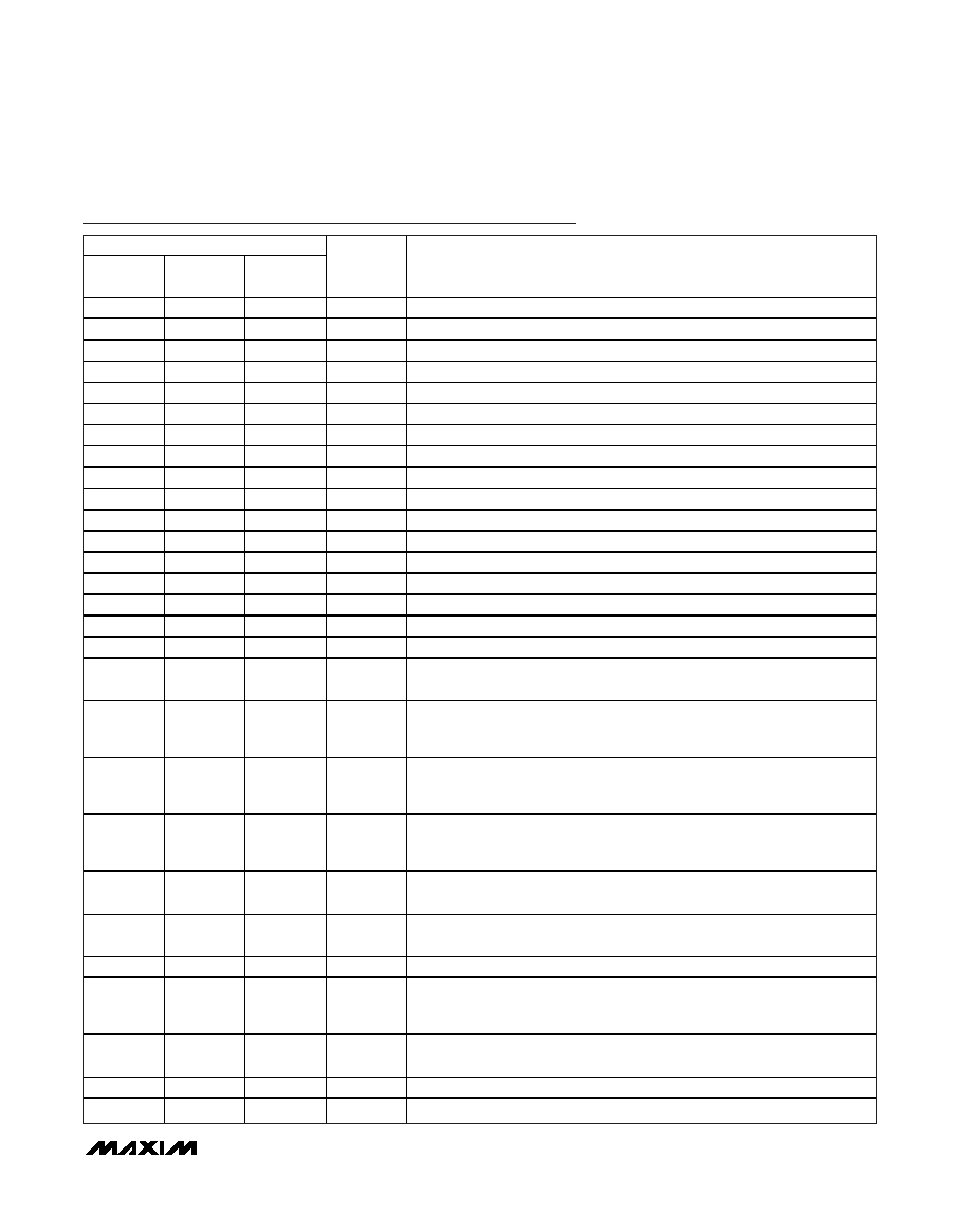
Pin Description (continued)
PIN
MAX11057
(TQFP-EP)
MAX11058
(TQFP-EP)
MAX11059
(TQFP-EP)
NAME
FUNCTION
1
DB12
14-Bit Parallel Data Bus Digital Output Bit 12
2
DB11
14-Bit Parallel Data Bus Digital Output Bit 11
3
DB10
14-Bit Parallel Data Bus Digital Output Bit 10
4
DB9
14-Bit Parallel Data Bus Digital Output Bit 9
5
DB8
14-Bit Parallel Data Bus Digital Output Bit 8
6
DB7
14-Bit Parallel Data Bus Digital Output Bit 7
7
DB6
14-Bit Parallel Data Bus Digital Output Bit 6
8, 22, 59
DGND
Digital Ground
9, 21, 60
DVDD
Digital Supply. Bypass to DGND with a 0.1F capacitor at each DVDD input.
10
DB5
14-Bit Parallel Data Bus Digital Output Bit 5
11
DB4
14-Bit Parallel Data Bus Digital Output Bit 4
12
DB3
14-Bit Parallel Data Bus Digital Output Bit 3
13
DB2
14-Bit Parallel Data Bus Digital Output Bit 2
14
DB1/CR3
14-Bit Parallel Data Bus Digital Output Bit 1/Configuration Register Input Bit 3
15
DB0/CR2
14-Bit Parallel Data Bus Digital Output Bit 0/Configuration Register Input Bit 2
16
CR1
Configuration Register Input Bit 1
17
CR0
Configuration Register Input Bit 0
18
EOC
Active-Low, End-of-Conversion Output. EOC goes low when a conversion is
completed. EOC goes high when a conversion is initiated.
19
CONVST
Convert Start Input. The rising edge of CONVST ends sample and starts a
conversion on the captured sample. The ADC is in acquisition mode when
CONVST is low and CONVST mode = 0.
20
SHDN
Shutdown Input. If SHDN is held high, the entire device enters and stays in a
low-current state. Contents of the Configuration register are not lost when in
the shutdown state.
23, 28, 32,
38, 43, 49,
53, 58
23, 28, 32,
38, 43, 49,
53, 58
23, 28, 32,
38, 43, 49,
53, 58
AGNDS
Signal Ground. Connect all AGND and AGNDS inputs together.
24, 29, 35,
46, 52, 57
24, 29, 35,
46, 52, 57
24, 29, 35,
46, 52, 57
AVDD
Analog Supply Input. Bypass AVDD to AGND with a 0.1F capacitor at each
AVDD input.
25, 30, 36,
45, 51, 56
25, 30, 36,
45, 51, 56
25, 30, 36,
45, 51, 56
AGND
Analog Ground. Connect all AGND inputs together.
26, 55
RDC_SENSE Reference Buffer Sense Feedback. Connect to RDC plane.
27, 33,
40,48, 54
27, 33,
40,48, 54
27, 33,
40,48, 54
RDC
Reference Buffer Decoupling. Connect all RDC outputs together. Bypass to
AGND with at least an 80F total capacitance. See the Layout, Grounding,
and Bypassing section.
31, 34,
47, 50
31, 50
—
I.C.
Internally Connected. Connect to AGND.
37
34
31
CH0
Channel 0 Analog Input
39
37
34
CH1
Channel 1 Analog Input
发布紧急采购,3分钟左右您将得到回复。
相关PDF资料
MAX1104EUA+
IC CODEC 8BIT 8-UMAX
MAX11100EUB+
IC ADC 16BIT SRL 200KSPS 10UMAX
MAX11101EUB+
IC ADC 14BIT SRL 200KSPS 10UMAX
MAX11102AUB+
IC ADC 12BIT SPI/SRL 10UMAX-EP
MAX1111CPE+
IC ADC 8BIT LP 16-DIP
MAX1113CPE+
IC ADC 8BIT LP 16-DIP
MAX1116EKA+T
IC ADC 8BIT SERIAL SOT23-8
MAX11201BEUB+T
IC ADC 24BIT SRL 13.75SPS 10UMAX
相关代理商/技术参数
MAX11049ECB+T
功能描述:模数转换器 - ADC 16Bit 8Ch Simult Sampling RoHS:否 制造商:Texas Instruments 通道数量:2 结构:Sigma-Delta 转换速率:125 SPs to 8 KSPs 分辨率:24 bit 输入类型:Differential 信噪比:107 dB 接口类型:SPI 工作电源电压:1.7 V to 3.6 V, 2.7 V to 5.25 V 最大工作温度:+ 85 C 安装风格:SMD/SMT 封装 / 箱体:VQFN-32
MAX11049ETN+
功能描述:模数转换器 - ADC 16Bit 8Ch Simult Sampling
RoHS:否 制造商:Texas Instruments 通道数量:2 结构:Sigma-Delta 转换速率:125 SPs to 8 KSPs 分辨率:24 bit 输入类型:Differential 信噪比:107 dB 接口类型:SPI 工作电源电压:1.7 V to 3.6 V, 2.7 V to 5.25 V 最大工作温度:+ 85 C 安装风格:SMD/SMT 封装 / 箱体:VQFN-32
MAX11049ETN+T
功能描述:模数转换器 - ADC 16Bit 8Ch Simult Sampling RoHS:否 制造商:Texas Instruments 通道数量:2 结构:Sigma-Delta 转换速率:125 SPs to 8 KSPs 分辨率:24 bit 输入类型:Differential 信噪比:107 dB 接口类型:SPI 工作电源电压:1.7 V to 3.6 V, 2.7 V to 5.25 V 最大工作温度:+ 85 C 安装风格:SMD/SMT 封装 / 箱体:VQFN-32
MAX1104EUA
制造商:Maxim Integrated Products 功能描述:
MAX1104EUA+
功能描述:ADC / DAC多通道 8-Bit CODEC RoHS:否 制造商:Texas Instruments 转换速率: 分辨率:8 bit 接口类型:SPI 电压参考: 电源电压-最大:3.6 V 电源电压-最小:2 V 最大工作温度:+ 85 C 安装风格:SMD/SMT 封装 / 箱体:VQFN-40
MAX1104EUA+T
功能描述:ADC / DAC多通道 8-Bit CODEC RoHS:否 制造商:Texas Instruments 转换速率: 分辨率:8 bit 接口类型:SPI 电压参考: 电源电压-最大:3.6 V 电源电压-最小:2 V 最大工作温度:+ 85 C 安装风格:SMD/SMT 封装 / 箱体:VQFN-40
MAX1104EUA+TW
功能描述:ADC / DAC多通道 8-Bit CODEC +2.7V to +5.5V Single Supply RoHS:否 制造商:Texas Instruments 转换速率: 分辨率:8 bit 接口类型:SPI 电压参考: 电源电压-最大:3.6 V 电源电压-最小:2 V 最大工作温度:+ 85 C 安装风格:SMD/SMT 封装 / 箱体:VQFN-40
MAX1104EUA+W
功能描述:ADC / DAC多通道 8-Bit CODEC +2.7V to +5.5V Single Supply RoHS:否 制造商:Texas Instruments 转换速率: 分辨率:8 bit 接口类型:SPI 电压参考: 电源电压-最大:3.6 V 电源电压-最小:2 V 最大工作温度:+ 85 C 安装风格:SMD/SMT 封装 / 箱体:VQFN-40